How D.C. to A.C. Inverters Work

Igbt H Bridge Circuit Diagram

Igbt inverter Tahmid's blog: debugging the bridge: tips for successfully designing

65 3 phase inverter circuit diagram using igbt High voltage-current half bridge driver using ir2153 & igbt Igbt bridge configuration

65 3 PHASE INVERTER CIRCUIT DIAGRAM USING IGBT - InverterDiagram

7. igbt bridge configuration.

Igbt gate circuit figure drive power using improvement analysis magnet physics supplies based model

Igbts mosfets igbt mouser bipolarBridge igbt inverter problem motor grounding supply question Figure 3 from design analysis and improvement of an igbt gate driveIgbt converter buck gate appendix.

Ir2110 half circuit driver bridge drive mosfet using driving pwm voltage high mosfets bldc side gate low drivers typical singleBasics of mosfets and igbts for motor control Bridge circuit igbt work using invertersPower circuit diagram of an igbt based single phase full-bridge.

Buck-Boost converter, based on half-bridge IGBT modules with drivers

Igbt bridge inverters basics

Mosfet circuit moduleSingle phase igbt inverter. How d.c. to a.c. inverters workBuck-boost converter, based on half-bridge igbt modules with drivers.

Inverter igbt diode diagramsTheory of operation H-bridge igbt inverter problem on motorEasy h-bridge mosfet driver module for inverters and motors.

Single phase IGBT inverter. | Download Scientific Diagram

Inverter phase igbt igbts

Theory operation module igbt hardware bridge half wikiBasics of igbt full bridge inverters Igbt driver ir2153 voltage induction.

.
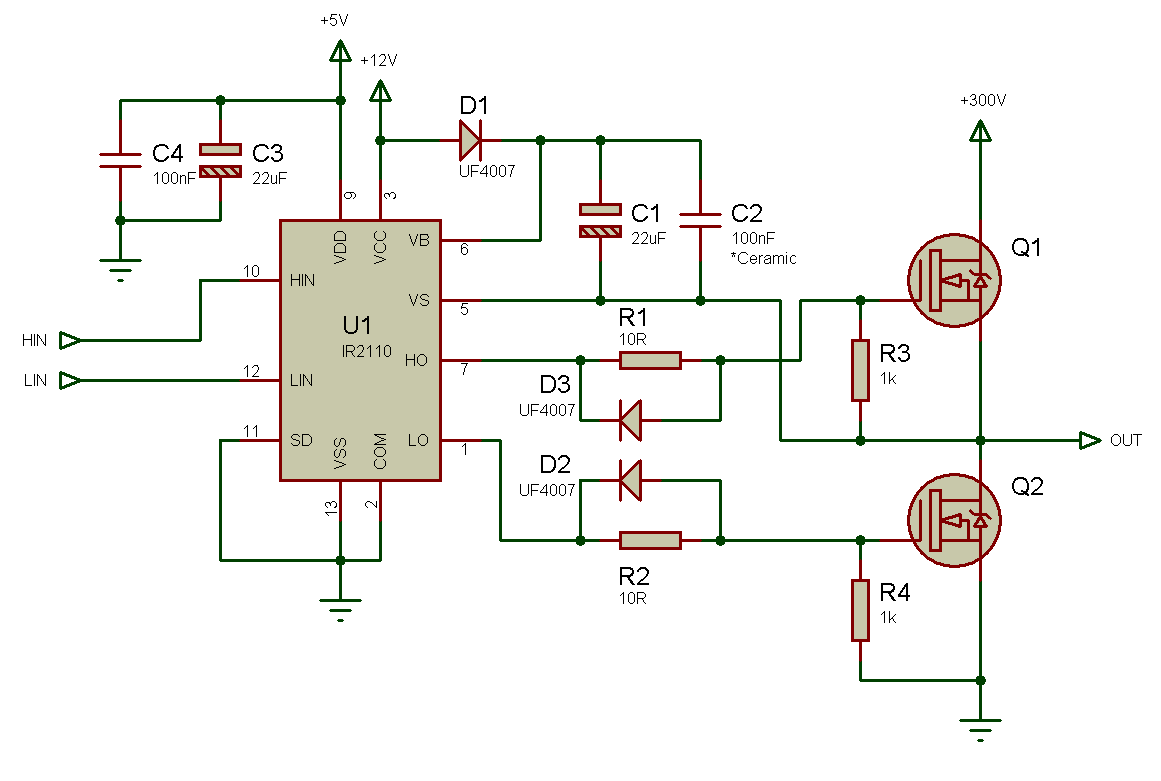
Tahmid's blog: Debugging the Bridge: Tips for Successfully Designing

High Voltage-Current Half Bridge Driver Using IR2153 & IGBT

Figure 3 from Design analysis and improvement of an IGBT gate drive

65 3 PHASE INVERTER CIRCUIT DIAGRAM USING IGBT - InverterDiagram

Basics of MOSFETs and IGBTs for Motor Control | Mouser

7. IGBT Bridge Configuration. | Download Scientific Diagram

How D.C. to A.C. Inverters Work

Easy H-Bridge MOSFET Driver Module for Inverters and Motors - Homemade

Basics of IGBT Full Bridge Inverters - YouTube

Power circuit diagram of an IGBT based single phase full-bridge